
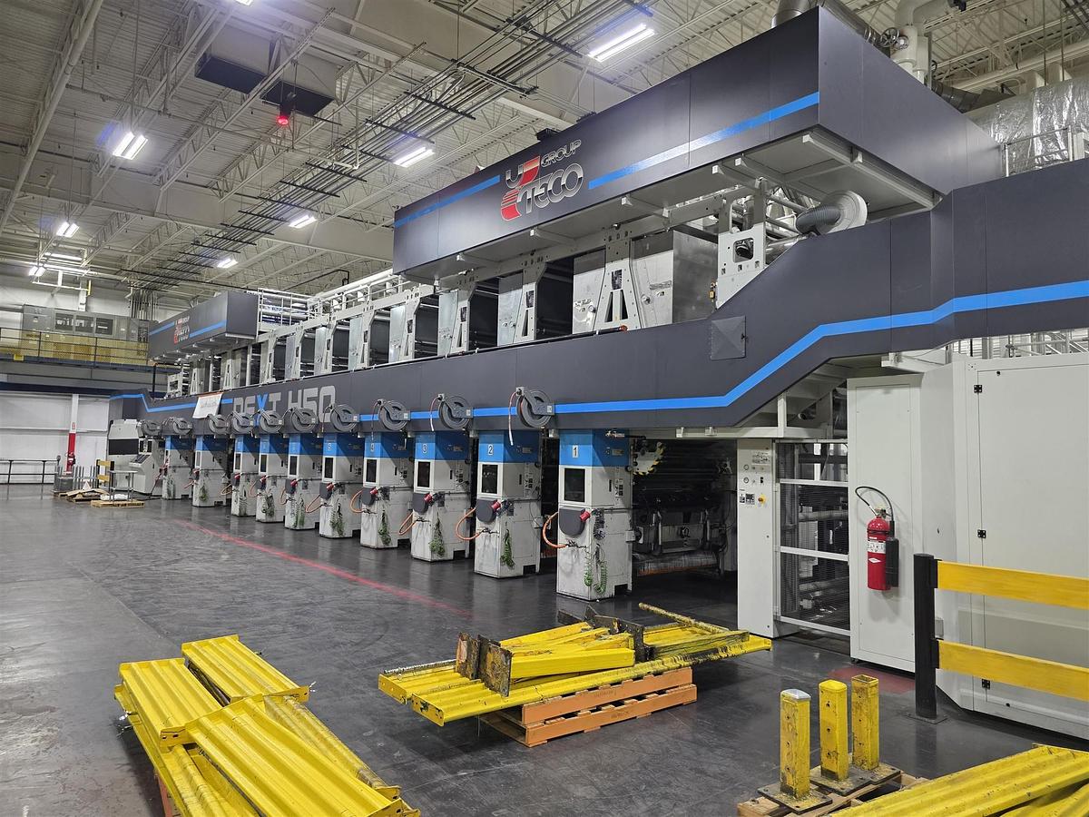
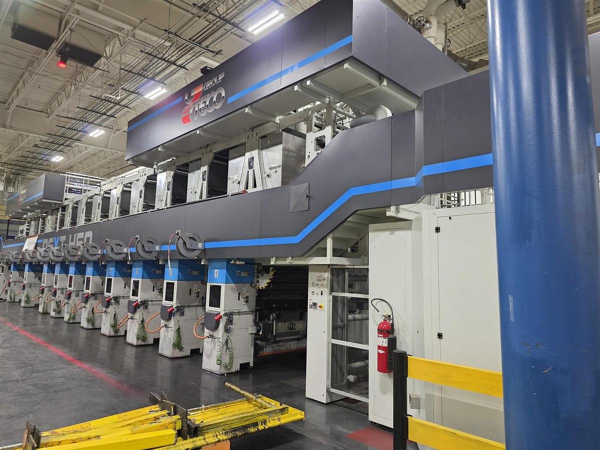
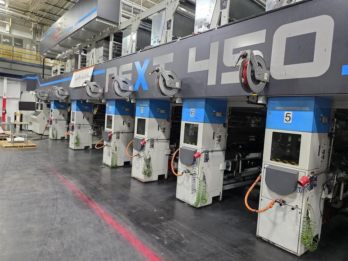
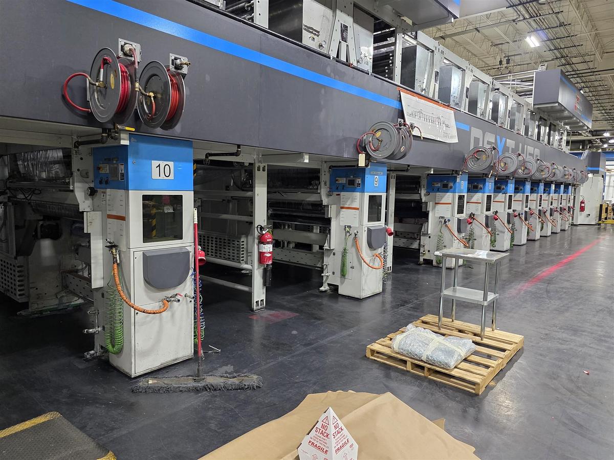
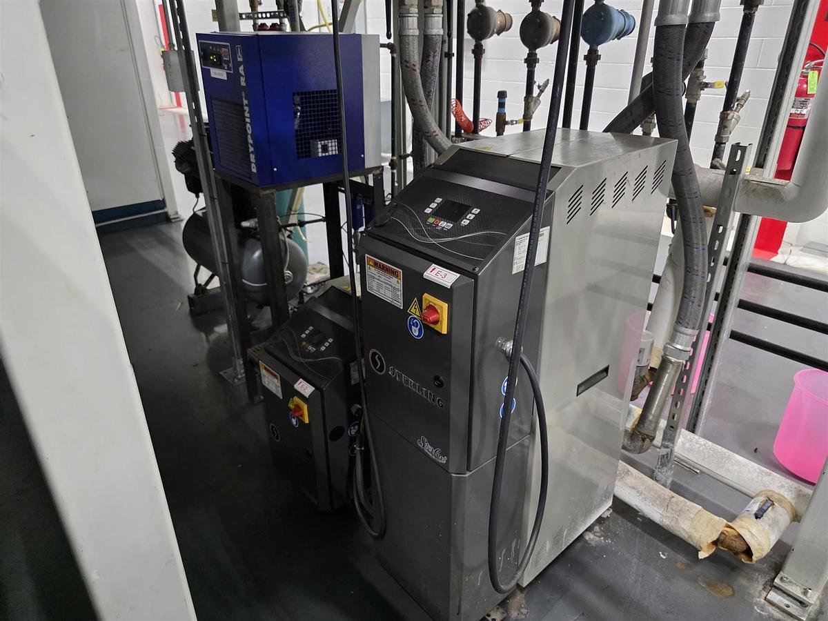
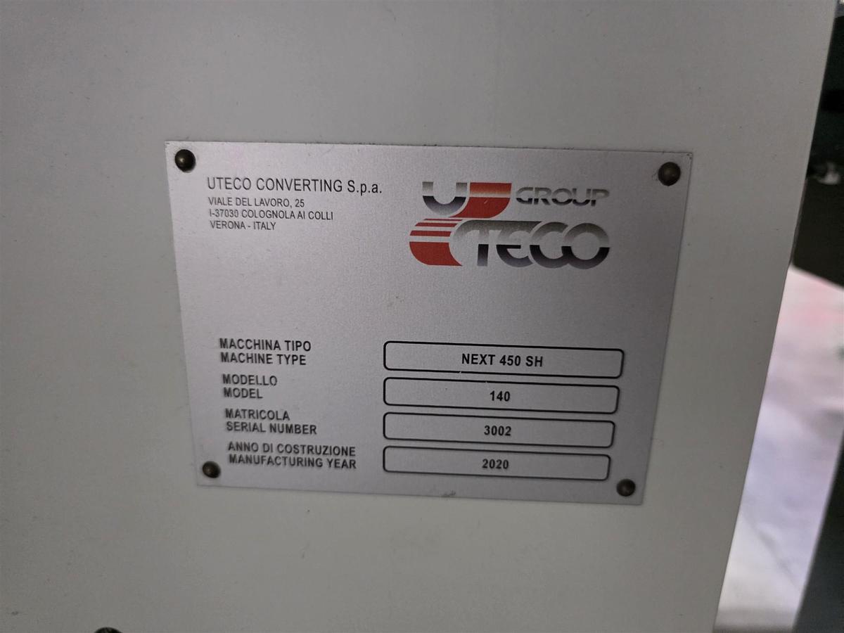
2020 Uteco Next 450 Rotogravure 10/C Press
Information
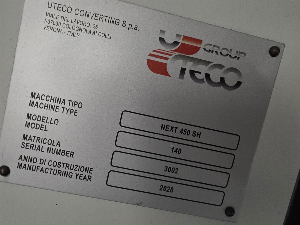
NEXT 450 10 C SL MOD 140
WITH SHAFTLESS CYLINDER MOUNTING
Electrical Shaft Rotogravure — 10 Colour Units Mod. 140
Manufacture Date: 2020 (Installed in 2022)
Technical Specification
MACHINE MAIN TECHNICAL FEATURES
Number of Printing Stations
Number of printing stations: 10, as follows
Number of single hood stations (C1): From printing unit 2 to 8 (7 units)
Number of double hood stations (C2): On printing units 1, 9 and 10 (3 units)
Material and Printing Width
Material width: 1450 mm
Printing width: max: 1420 mm (min.: 60% of the max. material width)
NB: In case of need of compatibility of the printing cylinders to existing cylinders in customer’s possession, Uteco may add extra costs for the modification of the line’s characteristics. The customer, anyway, will have to supply to Uteco the drawings of the existing cylinders for previous approval.
Printing Repeat
Printing repeat range: min. 450 mm (430 mm / 17")* – max. 920** mm
* With this repeat the maximum printing speed will be 300 m/min.
** Option 4 – largest possible cylinder repeat for machine.
Machine Speed
Mechanical speed: 450 m/min max
Printing speed – min.: 30 m/min (98 fpm) (depending on the type of inking system, type of inks, type of solvents and model of the machine)
Printing speed – max.: depends on all the following printing conditions:
• type of material;
• repeat of printing cylinders;
• inks, lacquers and solvents;
• required print quality;
• solvent retention level (if any);
• quality of the cylinders.
Reference Drawings and Web Direction
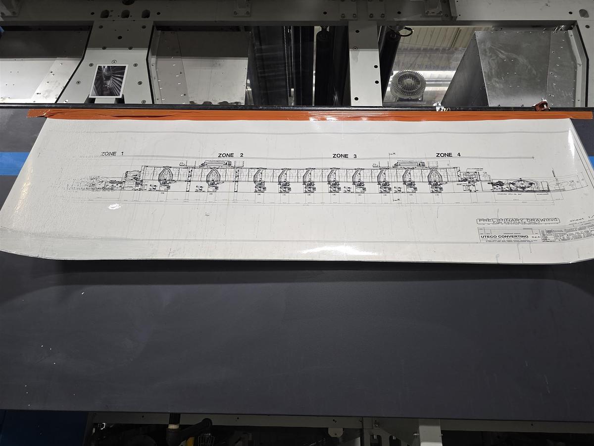
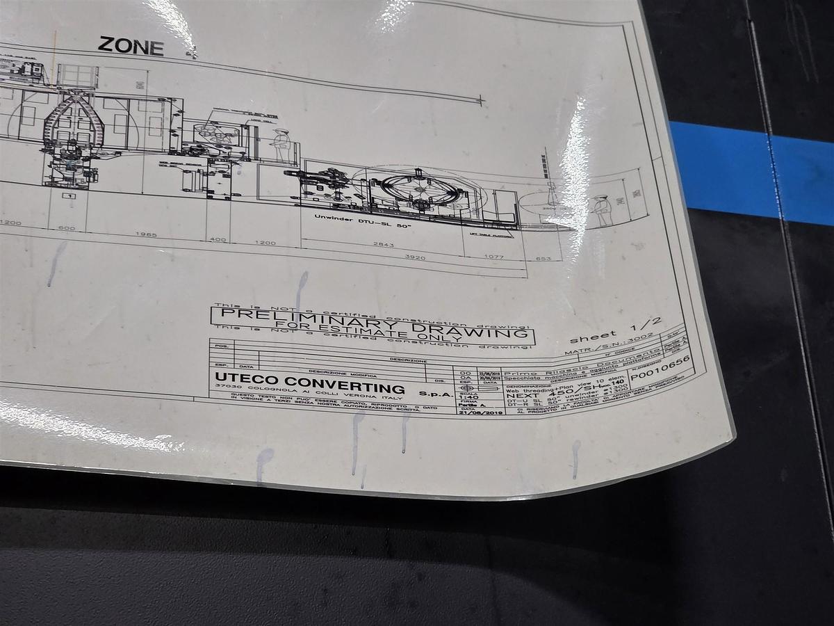
Reference drawings: web threading n° up-dated on; foundation plan n° (*) up-dated on (*)
Note: after the receipt of the reference drawings, for getting the definite version of the same, the customer must communicate to Uteco overall dimensions and requested special positioning to be verified by Uteco of the ducts for exhausted air evacuation. Uteco will proceed with the production of the machine according to the preliminary drawings in case no notice is received from the customer.
Web direction: From left to right
Type of Inks
Type of inks used: Solvent-based (the machine will be explosion-proof)
Materials to be Printed
Material / Thickness / Weight
OPP, BOPP, COPP: 12÷50 µm (48-20 ga)
PET-met. 9÷40 µm
PET 9÷40 µm
OPA 15÷60 µm
LAMINATES Max 100 g/m²
LDPE* 40÷50 µm (160-200 ga)
LLDPE* 40÷50 µm (160-200 ga)
PAPER** 22÷50 lbs/ream
PETG 50 µm (200 ga)
Polyethylene 40÷50 µm (160-200 ga)
Polyester 12÷40 µm (36-150 ga)
PLA 40÷60 (160-240 ga)
N.B.: thickness and width of the materials to be processed in the machine must match with the "tension range" specified here under. Furthermore low thickness flexible materials are subject to snap backs which have to be taken into consideration when choosing the proper printing parameters.
* This material must be suitable for rotogravure printing. The register tolerance is +/- 0,2 mm sigma 2. Maximum printing speed 200 m/min.
** Max web width and reel diameter limited to the machine’s tension range and reel weight.
Tension Range
Optimal tension range: 4 ÷ 48 kg for printing
Electrical Supply
Customer's plant power supply: 460 ± 5%
Machine voltage: 460 V – three phases with ground (T) and without neutral (N)
Main line frequency: 60 Hz ± 2% (if different, please specify)
Auxiliary voltage: 115 volts single phase (single phase line supplied by Supplier with transformer)
Services tension (supplied by the customer): 115 V single phase
Note: The customer must inform Supplier on the value of his own single phase tension for the maintenance plugs, provided in the electrical cabinet and for lighting.
Electrical standards: According to mentioned rules (see DIRECTIVES paragraph)
Colour of Machine
Color of machine: Standard for rotogravure presses — 1 White RAL 7035 + Red RAL 3000 + Grey RAL 7024
(*) Machine color refers only to the main structures manufactured and directly supplied by SUPPLIER. Any ancillary equipment not manufactured by SUPPLIER is painted according to current directives.
(*) Different colors, promptly requested by the customer, will imply an extra price.
Noise Level
Machine maximum noise level, only for equipment supplied by Uteco: within curve 85 dB (A) according to UNI EN 13023:2010 and UNI EN ISO 11204:2010 regulations.
NOTE: The noise level shall be measured at a distance of one meter (40") from the machine, in the operator console area and along the whole length of the machine, operator side. Readings shall be taken with only the UTECO machine running, and only when the insulated delivery/exhaust air vents (customer’s supply) are connected.
Environmental Conditions
Plant environment temperature: from 10° up to 40°C
Plant relative humidity: from 30 to 80% (at 20°C – 68°F)
Altitude: max 1000 metres (3300 feet) above sea level
According to specific room conditions, modifications to the press design could apply and consequently the quote overall price could be revised.
Directives
The press has been designed and manufactured according to NFPA 79 – UL 508A standards.
Any modification requested by the competent authority of the State of destination of the proposed equipment, must be carefully verified by Uteco in order to determine its technical feasibility. In case of such modification, it must be quantified in terms both of costs and production delays.
All the values regarding the tension (lb), speed (f.p.m.), temperature (°F), thickness (mil) on the machine will be indicated by using the Anglosaxon system.
Compressed Air and Chilled Water
Compressed air supply
Non-lubricated, dried and filtered:
• Pressure: 6 Bar — 86 PSI
• Dew point: + 2°C — 36°F
Non-lubricated, dried and filtered for cylinder clamps and pressor sleeve removal:
• Pressure: 16 Bar — 232 PSI
• Dew point: + 2°C — 36°F
• Air compressor 16 Bar (excluded from the scope of the supply)
Filtration clarity: less than 20 µ. Pressure: min. 2 bar (29 PSI) – max. 3 bar (44 PSI).
Chilled water specification
• Inlet temperature (chilled rollers, with room temperature 20°C / 68°F): 15°C to 18°C — 59°F to 65°F
• Hardness (Ca CO₃): 2.5 to 4 mg/lt — 2.5 to 4 ppm
• pH: 7 to 8.2
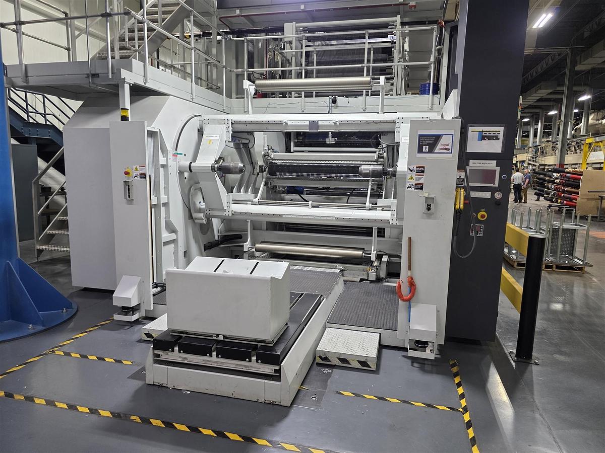
SHAFTLESS AUTOMATIC DUPLEX UNWINDER DTU-SL 1300 (50")
Fully automatic two reels unwinder for high production speed.
Main frames made of cast iron 70 mm (3") thick, mounted on a modular base plate connected with steel fabricated and centered cross members in order to guaranty no vibration at maximum machine speed.
Covers on the operator side and drive side containing drives and all the mechanic components.
Control desk on the operator side.
Minimum diameter of the reel to be loaded: 350 mm (14").
Max. reel weight 2600 kg.
The closing/opening of the frames is carried out by high precision linear slideways, and the reels catching through expansible mechanical hubs. The frames are moved by screws and controlled by pneumatical motors.
Adjustment of the side reel position by electric motor: +/- 25 mm (0,1").
Rotation of the reel crown by a peripherical motor reducer.
Reel change through toothed steel blades and pneumatically driven rubber pressure roller installed on a structure which moves horizontally. The movement is obtained by AC motor.
The maximum outside diameter of the reels is limited if 2 reels are simultaneously present at reel change, as follows:
Min. diameter at reel change 350 mm (14")
Max reel diameter shaft 1 1270 mm (50")
Max reel diameter shaft 2 (with max. reel on shaft 1) 1020 mm (40")
Max reel diameter with 2 alike reels on shafts 1 and 2 1140 mm (45")
Automatic splice in both directions.
The reel change sequence is started by the operator: rotation of the reel crown until the new reel reaches a photocell, forward feed of the group to the change position. Automatic rotation of the new reel; the diameter is automatically detected by an encoder (the calculation is carried out by PLC). After a few seconds both the pressure roller and the cutting knife are activated and the splice is carried out.
Safety Devices
The unit is equipped with safety devices according to mentioned directives (see DIRECTIVES paragraph).
Motor for Unwinder
Two unwinding stations each one driven by an AC motor.
Pneumatic Dancing Roller
Pneumatic dancing roll for the automatic control of the web tension.
Reel Change for Unwinder
Reel change through toothed steel blades and rubber pressure roller installed on a structure which moves horizontally.
The cut-off can be carried out in both unwinding directions and at production speed (according to used web and stickyback). No manual action is necessary to invert the cut-off group.
Automatic web cut-off can be carried out in two ways:
• By the operator control.
• When a minimum set diameter of the reel on unwinding operation is reached (set on HMI). The operator has to push the "Unwinder ready" button (new reel ready with tape is on the machine). Should the operator not push this button, the press stops decelerating when the minimum diameter is reached.
Regardless of the selected cut-off choice, other two additional functions can be carried out by the operation, to be selected from HMI:
• "Synchronized change of the reel" between unwinder and rewinder (only if the rewinder features this option). This function automatically starts the reel change on the rewinder and cuts as soon as the splice reaches the same rewinder.
Remark: With high-speed printing presses, when featuring the reel change, the machine will slow down to the max speed set on HMI. The slowdown is automatically carried out before the reel change. After this operation the machine returns to nominal production speed.
Chucks Supports — N° 2
Chucks supports.
Self-Expanding Chucks
• N° 2 — 2 (two) self-expanding chucks for cores i.d. 152 mm (6").
• N° 2 — 2 (two) self-expanding chucks for cores i.d. 76 mm (3").
Reels Loading / Unloading
Reels loading and unloading system by means of hydraulic platform, complete with trolley with manual side movement for the centering of the reel. The platform must be embedded on the floor.
When the table lifter is working, inter-lock system will prevent the unwinder or rewinder from rotating.
Edge Guide OPG — N° 1
Edge guide OPG, electromechanical type, with dual ultrasonic sensors, for edge or changeable center line reading, adjustable by two independent electrical motors.
Tension Readout by Load Cell — N° 1
Corona Treater brand ENERCON — N° 1
(with touch screen controls integrated into Uteco HMI)
Corona treater for conductive and non conductive materials, for the treating of one side only of the material. Enercon Corona Treater composed by:
• Station Diagnostic Panel
• Watt Density / Proportional Speed Control
• Computer Interface
• Remote Control
REMARK: This treating system is intended for the refreshment of pre-treated materials only (pre-treatment level: 34/36 dynes). The refreshing increases the pre-treatment level by + 4/+6 dynes, provided that the wax content does not exceed 500 ppm (anti-blocking max. 1%).
NOTE: The ozone (polluting agent), produced by the corona treater stations, may require an abatement system according to the local regulations.
Motorization supplied by Uteco as well as dancing roll and load cell for web tension monitoring only. The Corona treater functions as infeed nip roll too.
PRINTING GROUP
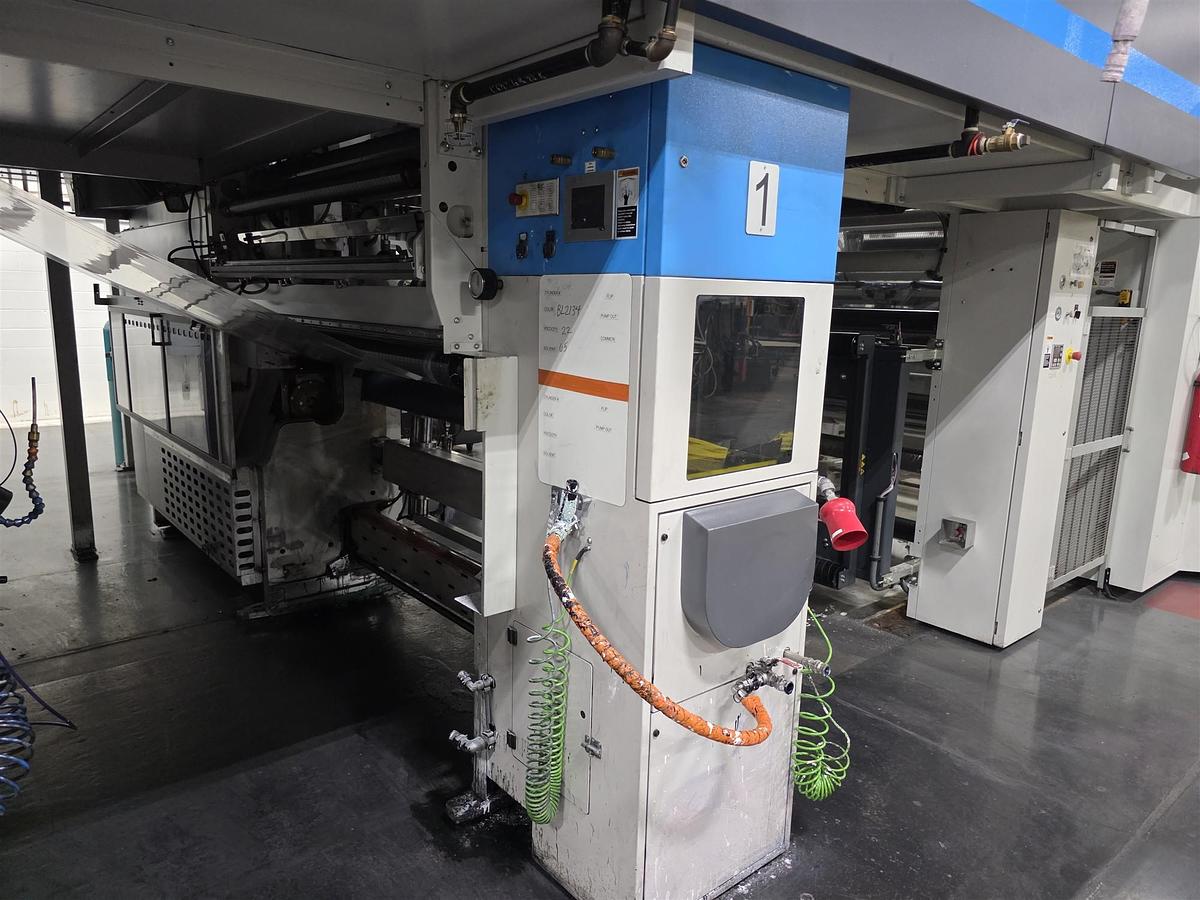
The printing sections are composed as follows:
• 7 (seven) units type single hood C1 on colors: 2-3-4-5-6-7-8
• 3 (three) units type double hood C2 on colors: 1, 9 and 10
Each unit is composed as follows.
The printing stand is the structure that includes all the equipment to print, thread and dry the web.
• Steel frames 70 mm thick, with steel strengthening bars.
• Aluminium idler rolls, dynamically balanced.
Pressure Group — N° 1
Vertical motion pressure group, placed on high precision linear slideways. Slideways are backlash free to grant the best precision when setting the pressure and constant repeatability of the different working conditions.
Pressure rubber roll (or pressure roll), sleeve-type, of 160 mm external diameter. The pressure cylinder is pneumatically loaded on the gravure cylinder.
Max. printing pressure: 10 kg/cm
The vertical movement of the pressure cylinder is independently adjusted on both sides by means of two low friction pneumatic pistons.
Automatic throw-off of the pressure roll at the press stop.
Pressure Roller Sleeve — N° 1
Sleeve of about 12 mm thickness. (Recommended features for rubber hardness: for PE: 70 shore – for BOPP/PP: 80 shore – for ALU/PAPER: 90 shore).
THE CUSTOMER MUST SPECIFY TO UTECO THE HARDNESS OF THE RUBBER.
The sleeve change is activated by the operator through a dedicated button and no tool is requested.
The sleeve is inserted and disinserted operating pneumatically on the steel mandrel. The insertion/disinsertion is effected through a circular slot, placed in the printing section on operator’s side. The sleeve can be inserted and/or disinserted with the film in tension.
Doctor Blade Group — N° 1
Blade group, placed on the side frames of the printing unit, sliding on low friction ball bushings.
Side run: ± 8 mm adjustable by means of an eccentric system. Oscillation through motor controlled by inverter. The blade pressure is effected by two pneumatic pistons.
The support group of the blade is adjustable with precision in height and parallelism. And to operate with different angles of blading some reference indicators are available for each setting as to grant the repeatability of the different working conditions.
Blade holder equipped with an eccentric type blade blocking system which allows the removal/placing of the blade with no need of any further tool.
Target blade position and actual position angle are displayed on the touch screen panel. The operator will manually adjust the blade position on the base of the target angle displayed.
Adjustable Roller — N° 1
Adjustable roll at web infeed of the printing unit. It is positioned by 1 (one) micrometric screw and it operates when needed (if the material is not threading uniformly).
MOVEMENT OF THE PRINTING GROUP
Drive of the Printing Unit
Each printing unit is driven independently by means of a servo motor in electronic line shaft.
The drive is also used for the slow automatic rotation of the printing cylinder at the machine stop.
Insertion and disinsertion of the gravure cylinder to the transmission of the motor is by means of the automatic clamp with Uteco shaftless type system.
Cylinder Clamping
The cylinder clamping is automatic through pneumatic and mechanic pincers.
A laser spot positioned on the transmission side allows to visualize the register mark on the printing cylinder and set then the pre-register among all the printing units.
Rotogravure Cylinder
The gravure cylinder is placed on the frames of the printing unit by means of printing trolleys.
Solvent Fumes Exhaustion
Solvent fumes exhaustion at the bottom of the printing unit. The air is extracted from the bottom of the printing unit and sent to the fresh air duct.
Side Register
All printing units are equipped with motorized side registers by means of brushless motors. Maximum possible adjustment: ± 10 mm.
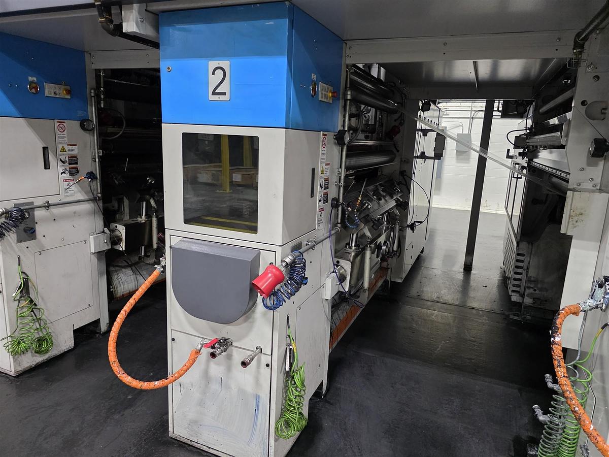
Control Panel
The control panel is placed on the operator side of the printing section and allows the following:
• pressure and movement of the pressure roller
• press stop, impulse and emergency stop
• pressure and movement of the doctor blade
• control drive of the longitudinal and side registers
• engage and disengage of the trolley
• engage and disengage of the cylinder
• pumps on/off
• slow rotation on/off
• doctor blades pressure
Operator Panel
SMART PACK’s operator panel is located on the printing group, operator side, and is equipped with the following control: 1 (one) 5" touch screen colour monitor with following main pages on the menu:
• line speed: view – modify
• temperature control: view – modify
• diagnostic message: view
• pressure and drive of the pressure roller
• washing sequence
• number of the station
• clock
• remote control of ESA system (if any)
• remote control of Viscosimeter
• colour of the ink in use
• remote control of LEL
• pressure control of the doctor blade
• view of all functions of the trolley and printing cylinder
• register: view – modify
TROLLEY AND INKING GROUP
N° 10 trolleys included in the supply.
Trolley — N° 1
The printing trolley is very handy and easy to be controlled by only one operator. The trolley is automatic fixed on the machine. Automatic coupling with free trolley from the floor. Possibility to remove the cylinder only.
Tray — N° 1
Ink tray made of stainless steel. Their position is adjustable according to the different repeats of the printing cylinders, before to be inserted on the machine. The ink trays can be easily inserted and removed from the trolley.
The minimum volume requirement of the inking system to print is around 18 l.
Splash Guards — N° 1
Set of stainless steel splash-guards, installed on the sides of the tray, with the possibility to install the teflon guards on doctor blade side.
Filter — N° 1
The inking system is equipped with in-line magnetic and net filter.
Pumps — N° 2
Pneumatic pumps. The pumps are installed with ink inlet hoses on the front of the tray.
Ink Tank — N° 1
Stainless-steel tank of 45 litres positioned on the front of the machine, with the possibility to use the trading ink tanks.
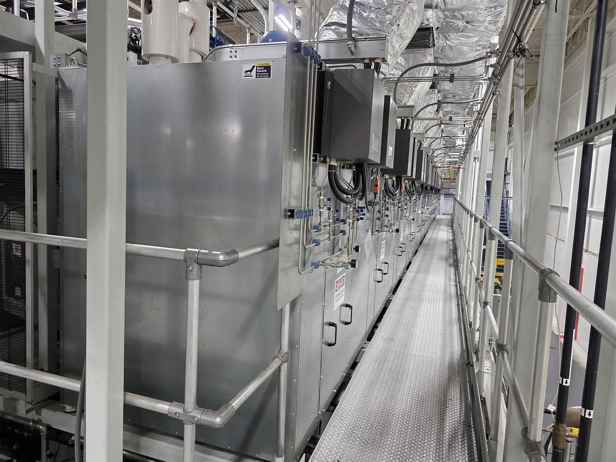
DRYING SECTION
Drying Hood Type C1 — for Units 2 ÷ 8 — N° 7 (seven)
Insulated drying hood of galvanized steel.
Ink is dried with hot air blown on the film, through nozzles which are built and installed so as to enable maximum efficiency and minimum energy consumption.
Aluminum idle rollers for web threading, under the hoods, outside diameter 80 mm.
MOTORIZED chill roll, situated at the exit of the drying hood (for quantity see the following table).
Technical characteristics
N° of zones with independent temperature: 1
Web path length of the hood: 2400 mm
Max. air temperature to the nozzle 100°C
with recycle: 50%
considering in-take air temperature: +20°C
N° of nozzles for each hood: 14
Max. air speed to nozzles: 40 m/s
N° of motorized low friction chilled rolls for each hood: 1
Hood opening
The longitudinal opening of the hood is by means of pneumatic piston. Opening the hoods it is possible to thread the web, clean the rolls and nozzles.
Drying system — for each unit the supply includes
• 1 (one) Diathermic oil heat exchanger, temperature 230°C and pressure 3 bar
• 1 (one) Temperature control
• 1 (one) Pneumatic 3-way valve for heating system included
• 1 (one) Structure for the ducts
• 1 (one) Blowing fan — air volume at the hood (to be specified) m³/h with inverter
• 2 (two) Exclusion dampers except the printing stations which are not working
• 1 (one) Exhausting fan — air volume at the hood (to be specified) m³/h with inverter
Drying Hood Type C2 — for Units 1, 9 and 10 — N° 3 (three)
Insulated drying hood of galvanized steel.
Ink is dried with hot air blown on the film, through nozzles which are built and installed so as to enable maximum efficiency and minimum energy consumption.
Aluminum idle rollers for web threading, under the hoods, outside diameter 80 mm.
MOTORIZED chill roll, situated at the exit of the drying hood (for quantity see the following table).
Technical characteristics
N° of zones with independent temperature: 2
Web path length of the hood: 2400 + 2400 mm
Max. air temperature to the nozzle: 100°C
with recycle: 50%
considering in-take air temperature: +20°C
N° of nozzles for each hood: 14 + 14 = 28
Max. air speed to nozzles: 40 m/s
N° of motorized low friction chilled rolls for each hood: 2
Hood opening
The longitudinal opening of the hood is by means of pneumatic piston. Opening the hoods it is possible to thread the web, clean the rolls and nozzles.
Drying system — for each unit the supply includes
• 2 (two) Diathermic oil heat exchanger, temperature 230°C and pressure 3 bar
• 2 (two) Temperature control
• 2 (two) Pneumatic 3-way valve for heating system included
• 1 (one) Supporting structure for the ducts
• 2 (two) Blowing fan — air volume at the hood (to be specified) m³/h each with inverter
• 4 (four) Exclusion dampers except the printing stations which are not working
• 2 (two) Exhausting fan — air volume at the hood (to be specified) m³/h each with inverter
The first hood can be used also for preconditioning of the substrate.
Access Drying Hoods
Walkway to reach the hoods of the machine, for its inspection along from the first to the last printing unit.
2 (two) fixed ladders positioned on unwinder and rewinder side on rear side of the machine.
LEL System
Interface for LEL system supplied by Uteco. LEL system supplied by the customer.
NB: Printpack will provide the flame unit sensors (Control Instruments brand) to be integrated with the air recirculation system of Uteco and will ship to Uteco for installation of BOXES and provision of connections in duct, NOT PIPING. Space provisions needed and mounting brackets. Printpack will be responsible to install the above instrument and for the relevant piping.
OUT-FEED UNIT
Out-Feed Nip Roller — N° 1
Structure
• Structure of the frames: 45 mm thick steel.
• Aluminum idler rolls for web threading.
Out-feed chill rollers
1 (one) motorized iron chromium-plated chill roll having diameter 195 mm for the cooling and feeding of the web.
Cooling unit for the thermoregulation of the chill rollers INCLUDED.
Nip group
Integral rubber roller, driven pneumatically, to nip the web on the chill roller.
Transmission
The outfeed nip roller group is driven by an AC motor, controlled by a high-sensitivity dancing roll.
SHAFTLESS AUTOMATIC DUPLEX REWINDER DTR-SL 1300 (50")
Fully automatic two reels rewinder for high production speed.
Main frames made of cast iron 70 mm (2,7") thick, mounted on a modular base plate connected with steel fabricated and centered cross members in order to guaranty no vibration at maximum machine speed.
Covers on the operator side and drive side containing drives and all the mechanic components.
Control desk on the operator side.
Outside diameter of the cores: 95 mm (3,7") min.
Minimum diameter of the reel: 350 mm (14").
Max. reel weight 2600 kg.
The closing/opening of the frames is carried out by high precision linear slideways, and the reels catching through expansible mechanical hubs. The frames are moved by screws and controlled by pneumatical motors.
Rotation of the reel crown by a peripherical motor reducer.
Reel change through toothed steel blades and pneumatically driven rubber pressure roller installed on a structure which moves horizontally. The movement is obtained by AC motor.
The maximum outside diameter of the reels is limited if 2 reels are simultaneously present at reel change, as follows:
Max reel diameter shaft 1 1270 mm (50")
Max reel diameter shaft 2 (with max. reel on shaft 1) 940 mm (37")
Max reel diameter with 2 alike reels on shafts 1 and 2 1090 mm (43")
Automatic splice in both directions.
The reel change sequence is started by the operator: rotation of the reel crown, forward feed of the group to the change position. Automatic rotation of the new reel; the diameter is automatically detected by an encoder (the calculation is carried out by PLC). After a few seconds both the pressure roller and the cutting knife are activated and the splice is carried out.
Safety Devices
The unit is equipped with safety devices according to mentioned directives (see DIRECTIVES paragraph).
Pneumatic Dancing Roller
Pneumatic dancing roll for the automatic control of the web tension.
Motor for Rewinder
Two rewinding positions each one driven by an AC motor.
Reel Change for Rewinder
Reel change through toothed steel blades and gap rewinding system pneumatically driven installed on a structure which moves horizontally. The movement is driven by an AC motor.
The cut-off can be carried out in both rewinding directions. No manual action is necessary to invert the cut-off group.
A chromium-plated steel roll (ø = 215 mm) driven by a vector motor (brushless) through a toothed drive belt is positioned on the rewinder horizontally moving structure.
An integral rubber roller, pneumatically driven, works to nip the material along the nip roller. The operator can control the total web tension through a pneumatic dancing roller.
The material tension on the reel is determined by the sum of the tension generated by the nip roller on the reel external circumference (periphery) and the tension generated by the reel shaft motorization.
Through operator panel it is also possible to set separately the following:
• Web tension before the rewinder (on the dancing roll)
• Web tension on the center of the reel
• Web tension on the center of the reel with percentage reduction depending on the diameter (linear or hyperbolic function).
If the operator forgets to press the "rewinder ready" button, at the "star rotation" command the press stops decelerating.
Chucks Supports — N° 2
Chucks supports.
Self-Expanding Chuck — N° 2
2 (two) self-expanding chucks for cores i.d. 152 mm.
Edge Guide OPG with Platform — N° 1
Edge guide OPG, electromechanical type, with dual ultrasonic sensors, for edge or changeable center line reading, adjustable by two independent electrical motors (supplier at Uteco’s choice).
Reels Loading / Unloading
Reels loading and unloading system by means of hydraulic platform, complete with trolley with manual side movement for the centering of the reel. The platform must be embedded on the floor.
When the table lifter is working, inter-lock system will prevent the unwinder or rewinder from rotating.
Tension Readout by Load Cell — N° 1
WEB OUT-FEED UNIT
Videocamera Provision
Connecting structure and idler rolls for the future installation of a videocamera for front or back side printing inspection, including a white panel for transparent films inspection (not supplied when printing only on paper).
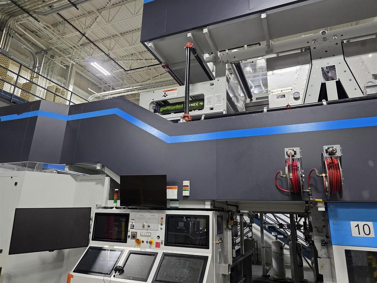
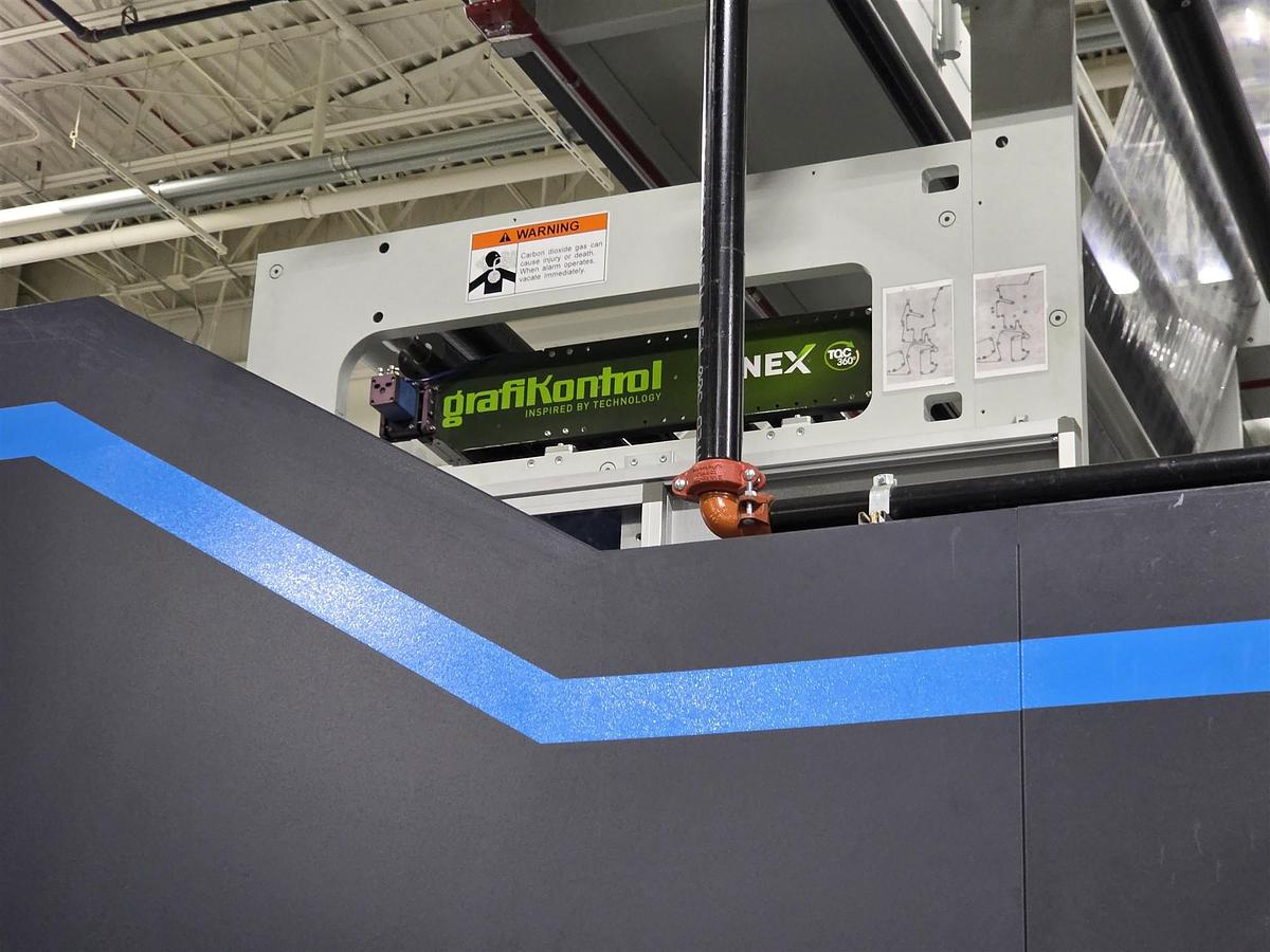
Videocamera for Printing Visualization
MATRIX 500 SYSTEM brand GRAFIKONTROL for the print visualization.
Main features
• Web viewing system with motorized zoom and traverse.
• ‘Full color’ image processing on any type of substrate by using an RGB matrix camera.
• Up to 30 camera positions storing with possibility to differentiate zoom, iris, and focus for each single image.
• Vertical and horizontal split screen function to allow the comparison of a printed image (live) with its master one, on the same monitor ("split image" function).
• Continuous scanning of the whole printing format, entering the data about the repeat of the cylinder and width of the material.
• Positioning of the videocamera by means of icons on the multi touch screen graphic interface.
• Manual and automatic camera preset in chosen positions.
• Zoom, iris and focus with video multi touch presetting.
• Internet connection for remote assistance.
Technical data
• 3-CCD digital camera with resolution 1600x1200 (6,0 Megapixel) with 16X optical zoom, with motorized lenses, with visualization area of 240 mm x 180 mm.
• 16X optical zoom, with motorized lenses.
• Lighting with High Flux Density (1000 Lh) LED in order to assure a quality and a light distribution without any degradation of the image also on metalized materials. The life of this component is unlimited.
• Operator interface is programmed for the maximum simplicity of use.
• High resolution LCD TFT 24" 16/9 multi touch screen monitor.
• Motorized and presettable traverse.
• Industrial personal computer with dedicated hardware for image processing.
• Ethernet interface.
Register Control BST – Eltromat model "REGISTAR_20"
1 completely wired mounting plate including:
• host system (IPC) with uninterruptible power supply
• XFC technology (eXtreme Fast Control)
• real-time I/O interfaces
• real-time control system
• job memory module (800 jobs)
• modularly expandable
• internal cables
Additional register control components
• Register control modules (one for each unit) for the control of the length and side register adjustment systems.
• Digitiser input modules (one for each unit).
• Register sensors (one for each unit): evaluating processor unit with intelligent 1-pixel color camera; 1 fibre optic lead for sequential register mark arrangement (CE0123 Ex II 2 G [Ex op is T4] IIB PTB 11 ATEX 2013 X).
• Sensing head bracket(s) 2-hole (one for each unit): 2-hole sensing head bracket with hexagonal bar SW 14.
• Profibus Interface I/O Signals — N° 1: Profibus interface for the exchange of I/O signals.
• Remote Maintenance Module — N° 1 (for diagnostics and maintenance via modem or LAN).
• Digitiser Input Module(s) — N° 1 (to connect non-eltromat digitiser signals).
• Fibre Optic Lead(s) (one for each unit) for dual-channel web-web measurement, incl. 6-hole bracket (CE0123 Ex II 2 G [Ex op is T4] IIB PTB 11 ATEX 2013 X).
PRS Quick Pre-Register System
The term "Presetting of the printing press" is understood as the procedure used to position the printing cylinders in phase one with the other as to achieve a printing register. This procedure yields significant time reduction during the set-up of a new job. This function is achieved through an industrial computer programmed by Uteco.
Functioning
• The cylinder position is sampled when the AMR code passes the sensor.
• The cylinder is adjusted and the pressure moves down.
• The controller detects the marks and is switched to automatic mode.
• The pre-setting is complete.
• All marks are in the gates and all controllers are in automatic mode.
• The press is ready to speed up.
Note: The AMR code must be placed on the first printing station.
ADDITIONAL ITEMS INCLUDED IN THE SUPPLY
Turning Bar — N° 1 (between printing units 8 and 9)
Printing possibilities: 8+2, 9+1.
• Steel frames and cross beams to grant high rigidity of the group.
• Chromium plated and drilled diagonal turning bars (diam. 120 mm) for overturning the material on air bearings.
• Supply fan for air blowing on supporting bars with adjustment of the blowing air. Air is blown from the holes along the length of the bars, avoiding contact between the material and the bars (air grease).
• Aluminum balanced idler rollers.
• Return of the overturned material into the next printing station, from above.
• Motorized movement of the bar for a perfect alignment of the web (+/- 15 mm) in respect to the next printing units.
• During the setting of the job the prepositioning of the bar is manually set, by means of push buttons, and then manually maintained and/or adjusted by the operator.
• Catwalk placed on transversal of the turning bar complete with a ladder.
Turning Bar — N° 1 (between printing units 1 and 2)
Printing possibilities: 1+9, 2+8.
• Steel frames and cross beams to grant high rigidity of the group.
• Chromium plated and drilled diagonal turning bars (diam. 120 mm) for overturning the material on air bearings.
• Supply fan for air blowing on supporting bars with adjustment of the blowing air. Air is blown from the holes along the length of the bars, avoiding contact between the material and the bars (air grease).
• Aluminum balanced idler rollers.
• Return of the overturned material into the next printing station, from above.
• Motorized movement of the bar for a perfect alignment of the web (+/- 15 mm) in respect to the next printing units.
• During the setting of the job the prepositioning of the bar is manually set, by means of push buttons, and then manually maintained and/or adjusted by the operator.
• Catwalk placed on transversal of the turning bar complete with a ladder.
ESA System brand ENULEC Direct Charge — N° 10
(integrated on Uteco HMI) Composed as follows:
• 10 Transformers ESA 1000-LD
• 20 Ionizers ESA 1000-EEx
• 10 Devices for Direct Upload a conductive fluid
Viscosity Control Uteco / GAMA — N° 10
Integrated on the HMI with the selection of 3 (three) different types of solvent.
In-line viscosimeter vibrating type G26 with sensor, operated by computer, for ink viscosity regulation and measurement. The viscosimeter’s interface is integrated in the Uteco operator panel.
It measures the viscosity controlling the response of the vibrating part by a unique technique of single sensor for drive and detect. The internal measure is translated into seconds (cup FORD-ZAHN).
If it is necessary to dilute the substance measured, a valve (ATEX valve) is used as to get the needed quantity of solvent to maintain the right viscosity. At the end of the job, the detector is cleaned together with the other parts of the machine.
NOTE: The solvent inlet system to the viscosimeter (pressure required: from 1 to 1,5 bar) is at customer’s charge.
Fire Fighting System
Supply system UTECO for signaling and extinguishing the principles of fire, in simultaneous protection of each printing element, composed mainly of:
On each printing unit:
• n° 4 nozzle dispensers
• n° 1 thermostat 80°C
For the whole line:
• n° 1 electrical panel
• n° 2 batteries 12 V 5.7 A
• n° 1 optical-acoustic warning
• n° 2 callpoints with glass to break (one top and one at the end of the line machine)
• n° 1 manual-electric actuator
General pipe connection along the machine INCLUDING provider — CO₂ cylinders and rapid flow valve are excluded from the supply (at the customer’s charge).
Automatic Pre-Washing Module "NEXT" Type
Each colour station is equipped as follows — 1 (one) washing module composed as follows:
• 11 (eleven) process valves mounted on two manifolds with pneumatic actuator which are respectively driven by 4 (four) pneumatic electrovalves, to regulate and select the inlet and outlet of the ink as well as the water flow (for cleaning purposes).
• 2 (two) pneumatic pumps: one for ink inlet and one for ink outlet from the ink trail.
• 1 (one) pulsation dampener on the ink inlet hose to the ink trail to guarantee a uniform ink pumping.
• 1 (one) filter positioned on the supply pipe of the tank.
• 1 (one) magnetic filter for keeping the metallic particles suspended on the ink due to the doctor blade wear.
To complete the washing system, the supply includes 1 (one) complete line for dirty solvent. The entire system is controlled by PLC.
Web Tension and Exhaust
• Every unit is equipped with tension readout by means of load cells.
• Web break detectors included on unwinder and rewinder.
• Exhausting ducts are equipped with filters to avoid accidental entrance of material parts in the drying system.
PRESS SUPERVISOR
RotoSmartPackEL, the Uteco engineering platform for improved performance and profitability in gravure printing for short and medium runs.
Machine Supervisor, composed with 1 (one) colour monitor touch screen of 24" SVGA (LCD). Dedicated software handles graphic presentation, as well as the real-time data exchange with the press.
Items included:
• Storage of data for up to 5000 jobs.
• Data transfer to a standard parallel printer (printer excluded), which consists in the supply of software to manage the serial of the printer for featuring set-up page printing and production trend printing.
Machine Automation
• PLC programmable logic control system, brand B&R, with remote peripheral units.
• 24 V input modules.
• Output modules with relays or Triac (when needed).
• Industrial computer to interface with the operator.
• UPS system for computer, included.
Teleassistance
The teleassistance allows Uteco engineers to verify, visualize and modify most of the electronic systems of the machine (PLC, HMI, OP, DRIVE).
The customer must foresee the connection of the machine to his company net as per a new user, communicating to Uteco all the data regarding the connection such as IP address, proxy, user name, password, etc.
To be sure that the teleassistance service works properly, the final user must:
• Be sure that the company network is not overloaded, since an overloaded network could prevent Uteco supplying this service.
• Be sure that from the connection point of the machine Router, the web site http://www.talk2m.net/ is accessible.
Uteco must supply: 1 (one) router including a firewall software.
The customer must supply: connection to the company network via Ethernet cable up to the Uteco Router inside the electrical cabinet.
It is advisable that the above-mentioned teleassistance line during its use is exclusively dedicated to the prearranged purpose. Uteco suggests to disconnect the router of the machine when it is not engaged with the teleassistance. This service includes (only during the guarantee period) free of charge assistance during Uteco working hours.
Help Line
Throughout the guarantee period, you can access free of charge technical support services via phone or remote connection (when available on the machine) from 8.30 am to 5.30 pm, Monday through Friday. At the end of the guarantee period these free services will fall into decay. Uteco Service Division will submit to the Customers new contracts for telephone assistance with the relevant subscription fees.
ELECTRICAL CABINETS
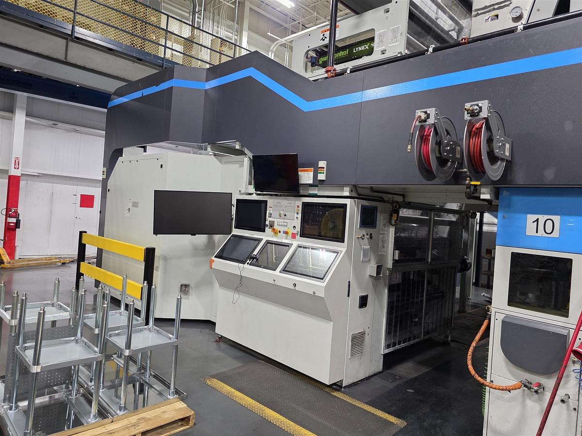
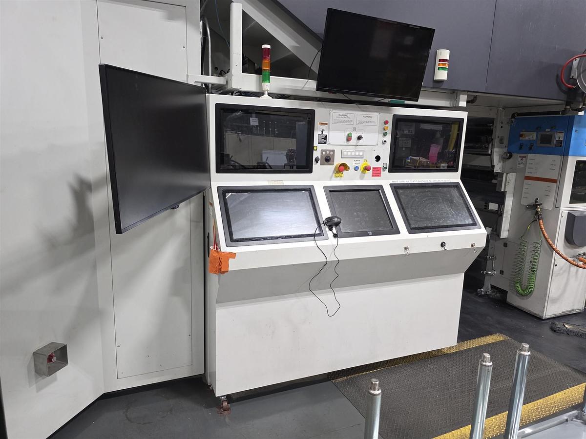
Main Operator's Control Console
Control console. The console is located on the operator side, in front of the outfeed nip-roll stand; its exact position is indicated on the foundation plan drawing. Any change to this position must be agreed with Uteco.
• Routing of cables between machine and console is via overhead wireway.
• Control console made of varnished steel sheet.
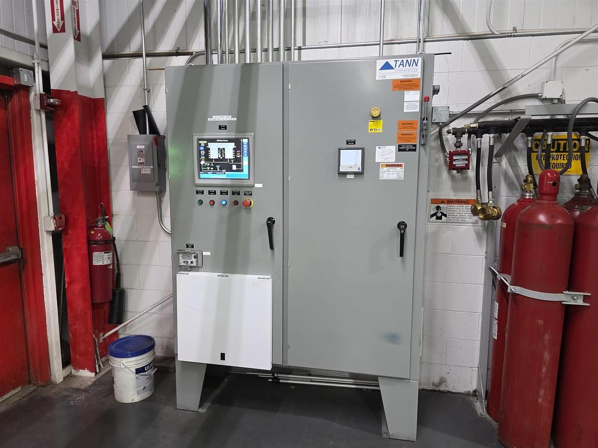
Electrical Cabinets
• Keyed locks.
• All components inside the electrical cabinets are provided with identification plates and all cables/binding clamps are numbered.
Main elements and devices included in the cabinets:
• motor drives
• machine master switch
• remote control switches
• overload switches
• fuses
• auxiliary relays
Position of Electric Cabinets
The electrical cabinets are located at about 2 meters (6.5 feet) on the rear side of the press (at floor level), starting from the edge of the nip-roller unit towards the rewinder (opposite direction in respect to the printing group). Their exact position is indicated on the foundation plan drawing. Any modification of this position to be agreed with Uteco.
Cooling of the Electrical Cabinets
The air conditioning of the electrical cabinets is included in the supply.
Lighting
Lighting points between the rotogravure units on the drive side.
Details
| Manufacturer | Uteco |
| Equipment Location | 1400 Abbott Drive, Elgin, IL 60123 |
| Auction Type | Private Sale |
| Inspection | By Appointment Only. All Inquiries Contact Tom Gagliardi at 203-671-4933 |